![]()
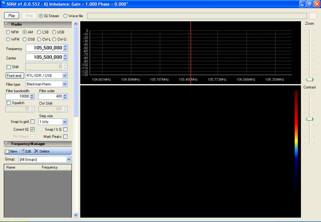
When you first start SDR#, a window should open looking similar to the above. You will notice that there is no frequency selected, and that the tuning indicator is tuned to “DC”. This is because there is no input device selected. In the examples that follow, the input device used will be a DVB-T dongle with a Realtek RTL2832u control chip and an Elonics E4000 tuner. Most DVB-T tuners based on the Realtek chip will work, and may include the E4000, FC0012, or FC0013 tuner chips. However, the actual tuning ranges and performance of the different tuner chips will vary.
The operating system shown is Windows XP SP3, SDR# version 1.0.0.552, the zadig USB driver has been installed, and Osmocom rtlsdr.dll copied into the SDR# install folder. See the INSTALLING SDR# section for details.
The main display is broken down into separate panels, each of which has a specific purpose. These panels may be set to default settings, and you may not need to adjust these. Feel free to become familiar with the purpose and operation of each setting. If you make changes that cause SDR# to become unresponsive or otherwise operate improperly, simply restarting the program will reset all settings to their default setting with the exception of the Frequency Correction (ppm) adjustment. See ADJUSTING FREQUENCY CORRECTION for details.
On the very top, you will see the Start and Stop buttons, with bullet selections for either IQ Stream or Wave File. Next to that is an interface to select a file if Wave File is selected. IQ Stream is the default selection, and the one we will use to capture a signal from the dongle.
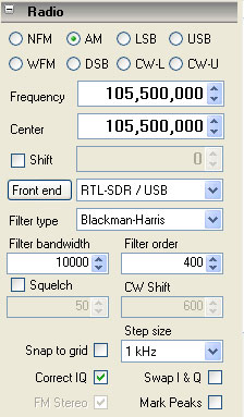
| NFM – Narrow FM | AM – Amplitude Modulation |
| LSB – Lower Side Band | USB – Upper Side Band |
| WFM – Wide FM | DSB – Double Side Band |
| CW-L – Continuous Wave Lower | CW-U – Continuous Wave Upper |
Frequency – The current tuned frequency.
Center – The current frequency of the center of the FFT display when NOT zoomed in. (NOTE: If a frequency is entered that is outside the current frequency range displayed by the FFT, the frequency will not change. Select a new Center that is the same or near the desired new Frequency).
Shift – This is to input an offset if an upconverter or downconverter is used so that the selected frequency is corrected to display the actual tuned frequency. Simply check the Shift box and enter your offset.
Front End / Input Select – The input select will allow you to choose your desired input device. A properly installed program will show;
RTL-SDR / TCP – RTL2832u device via TCP connection
RTL-SDR / USB – RTL2832u device via USB connection
FUNcube Dongle
SoftRock / SiS570
Other
Filter Type – This is to select the desired filtering type. Different filters will cause changes in the demodulated signal audio response curve due to differing envelopes and filtering profiles.
Filter Bandwidth – This is the effective width of the signal being processed for the mode selected. You can see the affected area in both the FFT and Waterfall area of the display when zoomed in, and you can either change the filter width here, or by dragging the outer edge of the grayed out area in either live display.
Filter Order – A modifier for the selected filter. The default setting works for most applications.
Squelch – Turn squelch on, and select the level with the box below it. Squelch levels may change depending on filtering type and mode selected.
CW Shift. – Changes the frequency shift in either CW mode. Similar to changing a BFO (Beat Frequency oscillator).
Snap To Grid – Forces frequency to snap to frequency steps selected when drag tuning.
Correct IQ – Enables SDR#’s exclusive Automatic IQ Correction.
Swap I & Q – Swap I & Q inputs. Useful when using sound card input devices Swaps L/R inputs to I/Q
FM Stereo – Select FM Stereo demodulation when using WFM with broadcast FM radio
Mark Peaks – Displays a marker on detected peaks above the noise floor.
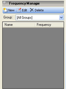
New – Adds the current frequency/mode/center to the frequency.xml file located in the SDR# folder.
Edit – Edits the current selected frequency from the visible list.
Delete – Deletes the current selected frequency from the visible list.
Group – Displays a user defined group, [All Groups], or [Favorites].
The list displayed for the current selected frequency group may be sorted by either Name or Frequency in either direction by clicking the title bar at the top of either column.
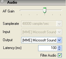 AF Gain – Volume Control.
Samplerate – May not be highlighted or adjustable, depending on the input device selected.
Input – Input source. May not be highlighted or adjustable, depending on the input device selected.
Output – Audio output control. Useful if multiple sound cards or Virtual Audio Cable (VAC) is used.
Latency – Audio delay in milliseconds.
Filter Audio – Enables a passband filter for audio output. Uncheck if using software to decode POCSAG or other digital modes.
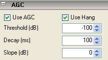 Use AGC – Select or deselect AGC.
Use Hang / Threshold / Decay /Slope – Modifiers to adjust ACG response and behavior.
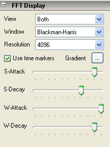 View – Select either FFT display, Waterfall, or both.
Window – Select FFT processing type;
None
Hamming
Blackman
Blackman-Harris
Hamm-Poisson
Youssef
Each filter has different response curves and envelopes.
Resolution – Display resolution from 512 to 4194304 by powers of 2. 4096 is the default selection. NOTE: Processing overhead increases with higher resolution settings, and may cause erratic operation or audio stuttering if too high a resolution is selected. 16384 appears to be a good selection for display/performance compromise.
Use Time Markers – Displays Date and Time markers on the left side of the Waterfall display every 10 seconds with default settings in the SDR# config.
S-Attack / S-Decay / W-Attack / W-Decay – These all affect the response and appearance of the FFT and Waterfall displays.
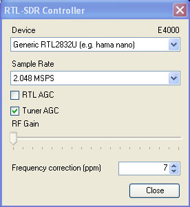 Device – Used to select the desired device if more than one is connected. It will also display the detected tuner type for RTL front end tuners.
Sample Rate – Available sample rates for the selected device is displayed. Lower Sample rates will cause a narrower bandwidth to be displayed on the live displays (FFT & Waterfall). A higher rate will display a wider bandwidth. Too high a bandwidth may cause dropouts, stuttering or other problems.
RTL AGC – Enable AGC in the Realtek 2832u front end.
Tuner AGC – Enable AGC in the tuner.
RF Gain – Available gain setting will be displayed and selectable for the detected tuner. Only available if Tuner AGC is deselected. This and the above two selections are for manual tweaking of the dongle .
Frequency Correction (ppm) – Adjust the tuner so that the displayed frequency equals the actual tuned one. See ADJUSTING FREQUENCY CORRECTION for operation.
Most if not all DVB-T dongles purchased for use as SDR devices will have errors in tuning. Remember, these are mass produced consumer items, not precision instruments. That being said, their operation is pretty impressive considering that most cost about $20 or so. The main problem is that the crystal acting as the master clock for the dongle is an unadjusted 28.8 Mhz device. Since the frequency error is completely linear over the tuning range of the device, an error correction in ppm (parts per million) can be used to adjust and correct the device at the software side of operation. This correction can be found in the Front End selection in the Radio panel.
The bottom selection is going to be used in this example of “tuning” your device so that the desired frequency is actually the one selected.
In this example we are going to be using a NOAA weather frequency in the US. Other locations may use any known local frequency. Selecting a constant broadcast one will make things easier, but an intermittent one will do if no other strong signal is available and you have a little patience.
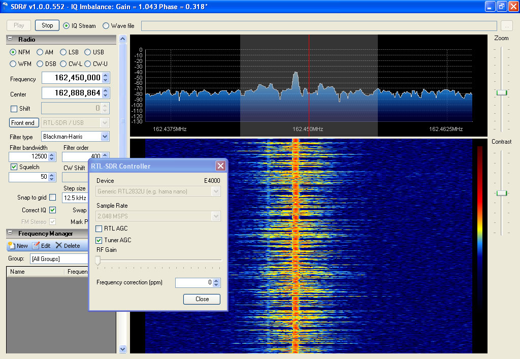
I will be using a NOAA Weather station located at 162.450 Mhz with my center tuned to 162.888 Mhz (approx). The actual Center frequency does not matter as long as the desired reference frequency is within the displayed range of the FFT.
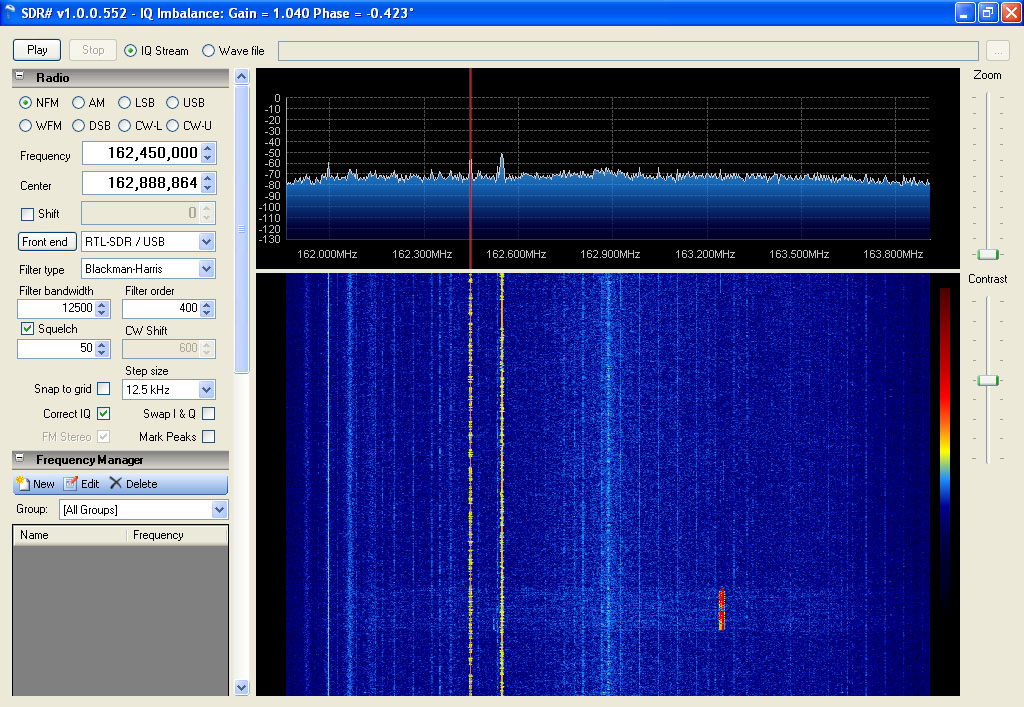
You will notice that the tuning indicator is located directly on the peak at that location indicating a properly tuned dongle. To achieve this there are only a few simple steps involved. Without any ppm adjustment (set to 0), the display may look more like the one below.
After tuning to the reference frequency, use the zoom control on the right of the FFT display to get a closer look at the frequencies signal pattern. Notice that the ppm correction is at 0, and that the tuning indicator does not line up with the center of the reference signal.
In the next step we us the up/down arrows to adjust the ppm correction to bring the tuning indicator to the center of the signal carrier. In the above example, the receive mode is NFM (narrow FM), and the carrier center is plainly visible.
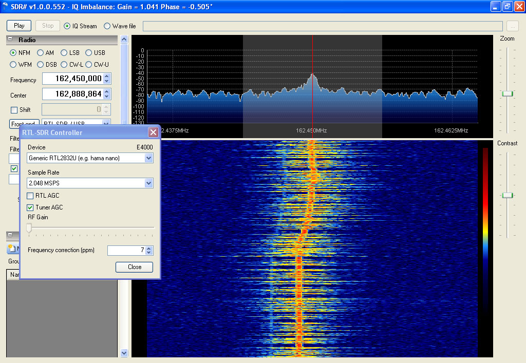
The carrier center is below the expected position on the display, so we will use the up arrow to add the ppm multiplier to the signal. If the carrier center was higher than the expected position (on the tuning indicator), we would use a negative adjustment.
One click at a time, bring the carrier center to line up with the tuning indicator. In this case it took a correction of 7. You will notice that every click walked the carrier slightly closer to the tuning indicator. You may notice that there is a slight overshoot to the right about half an inch down as 8 was selected, and then 7 was once again picked as the best correction factor. You may not get the indicator exactly centered because the ppm adjustment is an integer. Even so, it’s going to be more than accurate enough. You may want to write the ppm on the dongle itself as a reference. It is also recommended that you use the dongle for 15 or 20 minutes to let it warm up before adjusting, as frequency drift is affected by temperature.
SDR# is distributed in two separate zip files from the Downloads section of the SDR# homepage., WWW.SDRSHARP.COM. Due to licensing and packaging considerations, all of the required files needed to install SDR# have been split into two separate files, plus one more (rtlsdr.dll) that is available from the WWW.OSMOCOM.ORG website at http://sdr.osmocom.org/trac/attachment/wiki/rtl-sdr/RelWithDebInfo.zip. This filename and location may change, so check the OSMOCOM website for details.
From the Downloads page on the SDR# homepage, download the latest SDR# Dev release, and the latest SDR# RTLSDR Plugin. Both files will be in zip format and will extract using Winzip or Winrar. The contents of the main release zip should look something like this;
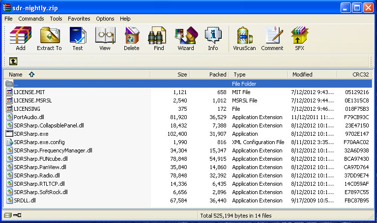
Extract all of the files in this zip to the folder/location of your choice. Next open the RTLSDR Plugin zip, and the contents will look similar to;
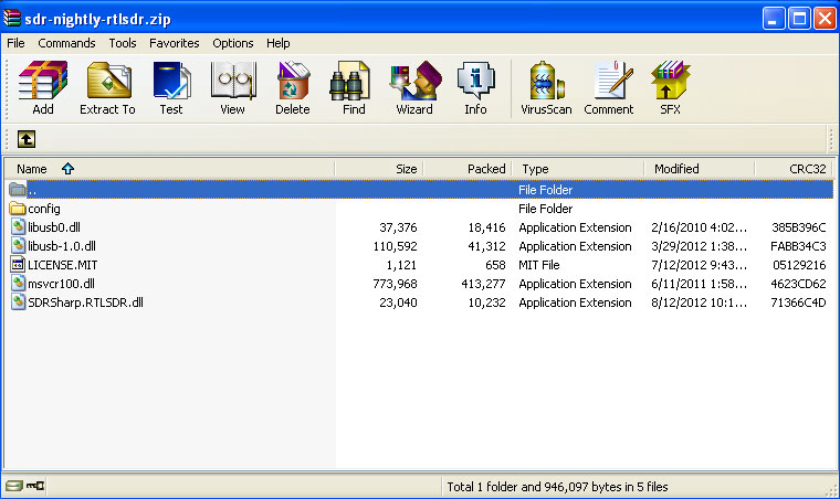
Extract all of the files to the folder where you installed the contents of the first zip. Notice however that there is also a folder contained in the zip, /config. This folder contains only one file, sdrsharp.exe.config. Move or copy this file into the parent folder, overwriting the existing file.
Next you will have to download the following zip; http://sdr.osmocom.org/trac/attachment/wiki/rtl-sdr/RelWithDebInfo.zip. The only file you will need is in the /x32 folder within the zip is rtlsdr.dll. Copy this file into the SDR# install folder. And that’s it.
The actual filenames, number of files, or packaging may change with future releases of SDR#, so only use these install instructions as a guideline. Any changes in the install procedure will be reflected here, so check back for the latest version.
One advantage of installing all of the files directly into a folder and not using an installer is that SDR# is completely portable. SDR# can be run directly from a thumb drive or network share. Just make sure all of the files are in a single folder, and run the SDRSharp.exe. Upgrades are equally simple. Just repeat with the contents of new version zip files. rtlsdr.dll should not have to be reinstalled as this file never gets overwritten. There is no need to uninstall to do an upgrade or make a program location change. Just overwrite the current files with the new ones, or move the folder and all its contents. The complete install folder may also be copied from one machine to another.
There is one additional step needed to get SDR# running with RTL based devices. Installing the zadig USB driver, replacing the default windows one. Full instructions and a link to the driver can be found at http://rtlsdr.org/softwarewindows. This driver MUST be installed successfully for proper operation of the dongle.
|
Documentation © 2012 Henry Forte
ver 1.2a - 8/18/12